ENGINEERED PROCESS EQUIPMENT · SINCE 1990
Heat transfer

Air Coolers

Air-cooled heat transfer for process and energy applications.
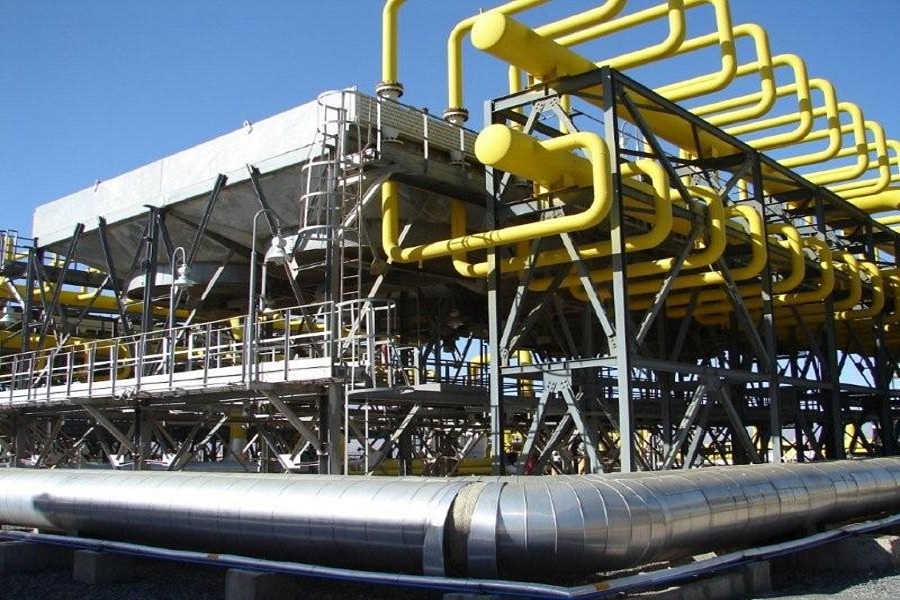
Air Coolers equipment
Equipment overview

Engineered for the application.

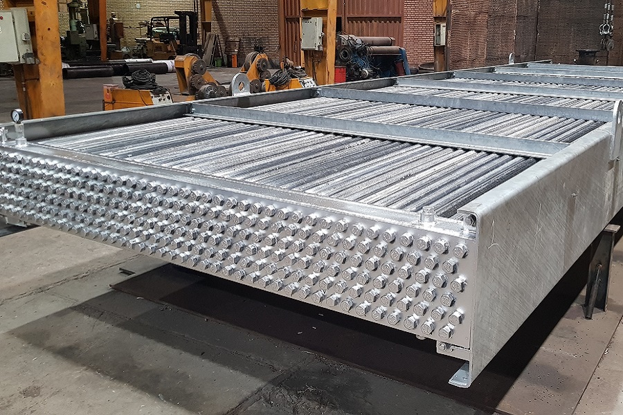
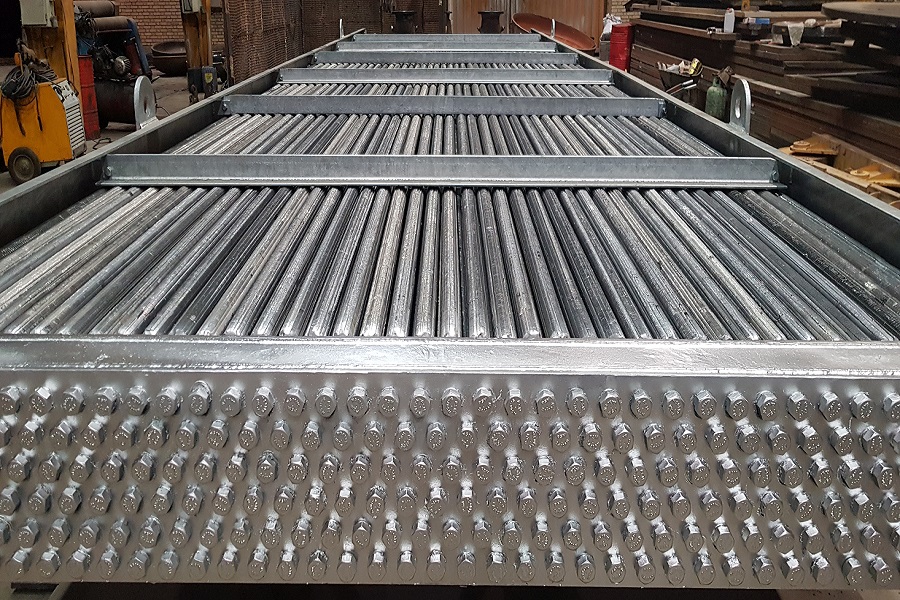
Air-cooled heat exchangers reject process heat to ambient air. Pars Technic supplies equipment configured around the required thermal duty, site conditions, and the mechanical requirements of each project.

Engineering scope

  • Finned tube heat-transfer surfaces
  • Fan and structural arrangements tailored to the installation
  • Process cooling for oil, gas, and energy facilities
  • Design coordination with project layout and access requirements

At a glance

Air Coolers — equipment summary
EquipmentAir-cooled heat exchangers
Cooling mediumAmbient air
Design inputsDuty, ambient conditions, process flow, and installation constraints
ApplicationsGas and liquid process cooling
How it works

One air cooler bay, at any fan speed.

Process liquid runs through rows of finned tubes; two fans under the bundle push ambient air up through them. Change the fan speed: the air flow, the fan power and the outlet temperature all follow one model.
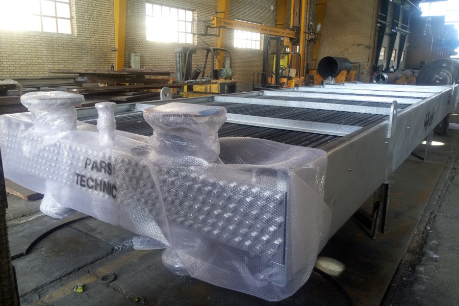
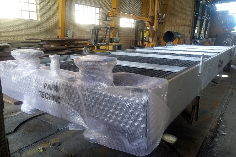
Fan blades: what the speed control drivesAir rising through the plenum and leaving the bundleBundle 6.0 × 2.4 m: 4 rows, 134 finned tubesAn illustrative bay: two 2.1 m fans under a 6.0 m bundle cool 8.0 kg/s of light hydrocarbon liquid (cp 2.3 kJ/kg·K) from 120 °C with air at 35 °C. Air flow follows fan speed and fan power its cube (fan laws): 13.3 kW at full speed, 1.7 kW at half. The outlet temperature comes from an ε-NTU crossflow model, both fluids unmixed, with UA 34.0 kW/K at full speed whose air-side part scales with air velocity to the power 0.68; the heat the liquid gives up is the heat the air takes away. Natural draft is neglected and the fans are drawn turning slowly. Values are illustrative; each cooler is designed to its own data.
From our archive

Equipment in focus.

Let’s build what’s next

Your next project starts with a conversation.

Talk to our team