A heat exchanger is a device used to transfer heat between two or more fluids. The fluids can be single or two phase and,
depending on the exchanger type, may be separated or in direct contact.
In order to discuss heat exchangers it is necessary to provide some form of categorization. There are two approaches that are normally taken. The first considers
the flow configuration within the heat exchanger, while the second is based on the classification of equipment type primarily by construction. Both are considered here.
Classification of Heat Exchangers by Flow Configuration
There are four basic flow configurations:
→ Counter Flow
→ CoCurrent Flow
→ Crossflow
→ Hybrids such as Cross Counterflow and Multi Pass Flow
Figure 1 illustrates an idealized counterflow exchanger in which the two fluids flow parallel to each other but in opposite directions.
This type of flow arrangement allows the largest change in temperature of both fluids and is therefore most efficient (where efficiency is the amount
of actual heat transferred compared with the theoretical maximum amount of heat that can be transferred).
In cocurrent flow heat exchangers, the streams flow parallel to each other and in the same direction as shown in
Figure 2, This is less efficient than countercurrent flow but does provide more uniform wall temperatures.
Crossflow heat exchangers are intermediate in efficiency between countercurrent flow and parallel flow exchangers.
In these units, the streams flow at right angles to each other as shown in Figure 3.
In industrial heat exchangers, hybrids of the above flow types are often found. Examples of these are combined crossflow/counterflow heat exchangers and multi pass flow heat exchangers. (See for example Figure 4.)
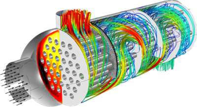
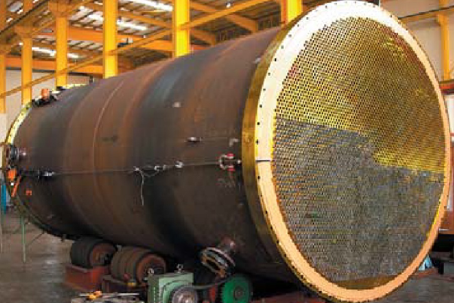
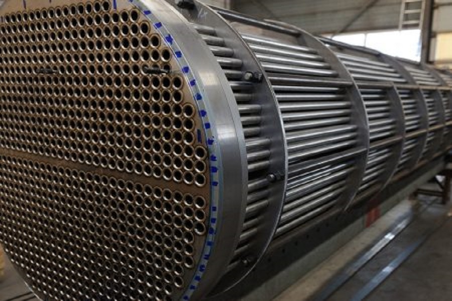
A Shell and Tube Exchanger consists of a number of tubes mounted inside a cylindrical shell.
Figure 5 illustrates a typical unit that may be found in a petrochemical plant. Two fluids can exchange heat, one fluid flows over the outside of the
tubes while the second fluid flows through the tubes. The fluids can be single or two phase and can flow in a parallel or a cross/counter flow arrangement.
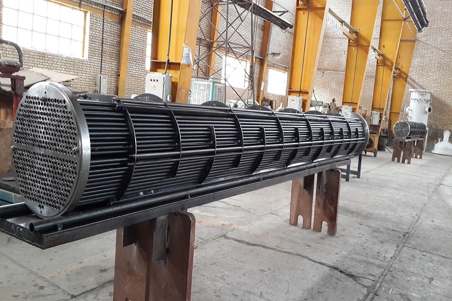
The shell and tube exchanger consists of four major parts:
→ Front end–this is where the fluid enters the tubeside of the exchanger.
→ Rear end–this is where the tubeside fluid leaves the exchanger or where it is returned to the front header in exchangers with multiple tubeside passes.
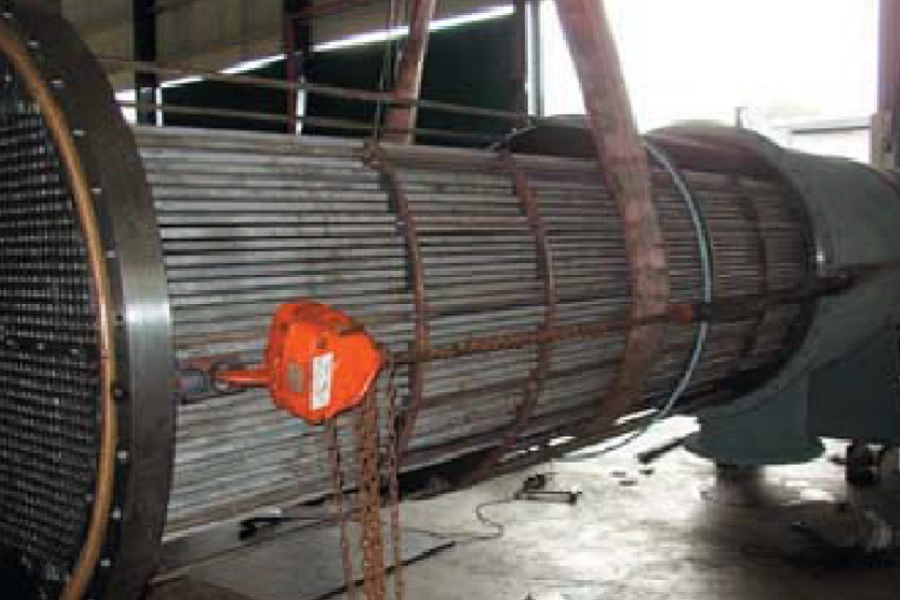
→ Tube bundle–this comprises of the tubes, tube sheets, baffles and tie rods etc. to hold the bundle together.
→ Shell—this contains the tube bundle.